


- Home
- About us
- ProductsProduct Classification
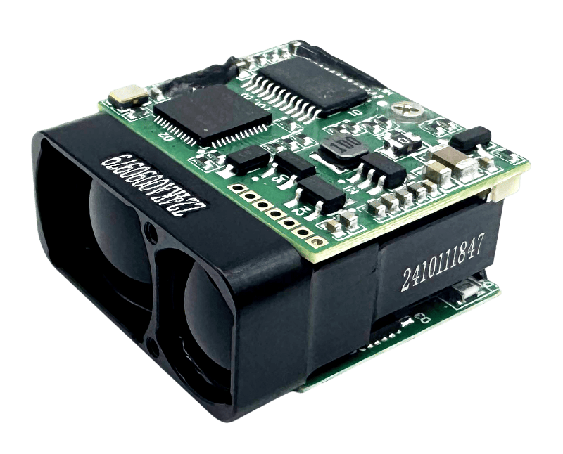
905nm B 1.5kmLaser Rangefinder Module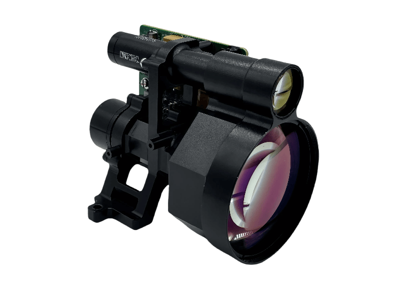
10.5km High-Accuracy 1535nmLaser Rangefinder Module 1535nm B 8kmLaser Rangefinder Module
 905nm 1kmLaser Rangefinder Module
 1064nm 20km/25kmLaser Rangefinding Telescopes
 1535nm 3.5km-10kmLaser Rangefinding Telescopes
 Multifunctional Binoculars 8kmInfrared & Laser Telescope
 Multifunctional Binoculars 3kmInfrared & Laser Telescope
 640 UncooledInfrared Module
 150A Single-AxisFiber Optic Gyroscope
 354A Tri-AxisFiber Optic Gyroscope
 - Blog
- Contact us
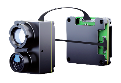

IR Series Uncooled Infrared Module – High-Performance Thermal Imaging Solution
The IR series uncooled infrared modules are advanced thermal imaging solutions developed by CHENGDU NEWTRON TECHNOLOGY CO., LTD. Designed with self-developed 12µm WLP-packaged high-refresh-rate detectors and 2nd-generation infrared ISP chips, these modules deliver exceptional performance across a range of demanding applications.
With resolutions of 640×512, 384×288, and 256×192, the IR series supports a wide operating temperature of -40°C to +85°C and a temperature measurement range of -20°C to +550°C. Their compact size, lightweight design, and low power consumption make them ideal for SWaP (Size, Weight, Power/Price) applications.
Key Features
High refresh rate across all series
Standard non-uniformity correction algorithm
High-quality imaging with sharp detail
Cost-effective and power-efficient
Application Scenarios
Drone Search: Electro-optical pods
Portable Devices: Handheld outdoor equipment, helmet-mounted night vision
Security & Fire Inspection: Industrial monitoring, perimeter scanning, inspection robots, fire warning systems, firefighting helmets
Smart Integration: Assisted driving, smart home appliances
Product Selection Guide
Lens Parameters
Note1: Detection, recognition, and identification distances are estimated based on the Johnson criteria, with a pedestrian (1.8×0.5×0.3m) as the target.
Note2: Weight refers to the lens only. Total weight includes the lens, module body, connector cable, and optional USB components.
Note3: FOV data is provided in Section 2.1
Note4: Depth of field refers to the maximum clarity range under fixed focus (e.g., glued or screw-fixed), not the adjustable focus range (typically 0.3m to ∞).Table1 Lens Parameters
| Lens | FOV (H×V) | Focal Length | F# | IFOV | Lens Depth of Field (DoF) | Detection Range | Recognition Range | Identification Range | Weight (Lens + Flange) |
|---|---|---|---|---|---|---|---|---|---|
| 9.1mm/ Manual Zoom | 19.3°×14.5° (256×192) | 9.1mm | 1 | 1.3 mrad | 1.73m~∞ | 1.1km | 0.25km | 0.17km | 10.5g±5% |
| 28.9°×21.7° (384×288) | |||||||||
| 48°×38.4° (640×512) | |||||||||
| 13.5mm/ Manual Zoom | 31.9°×25.7° (640×512) | 13.5mm | 1 | 0.9 mrad | 3.8m~∞ | 1.5km | 0.37km | 0.19km | 15.2g±5% |
| 15mm/ Manual Zoom | 11.7°×8.8° (256×192) | 15mm | 1 | 0.8 mrad | 4.7m~∞ | 1.7km | 0.42km | 0.21km | 20.48g±5% |
| 17.5°×13.1° (384×288) | |||||||||
| 18mm/ Manual Zoom | 24.2°×19.5° (640×512) | 18mm | 1.1 | 0.7 mrad | 6.14m~∞ | 2km | 0.5km | 0.25km | 25g±5% |
| 25mm/ Prime Lens | 7.0°×5.3° (256×192) | 25mm | 1 | 0.48 mrad | 13.02m~∞ | 2.8km | 0.7km | 0.35km | 67g±2% |
| 10.5°×7.9° (384×288) | |||||||||
| 17.5°×14.0° (640×512) | |||||||||
| 35mm/ Prime Lens | 7.5°×5.7° (384×288) | 35mm | 1 | 0.34 mrad | 25.52m~∞ | 3.9km | 0.97km | 0.49km | 111g±2% |
| 12.5°×10.0° (640×512) | |||||||||
| 55mm/ Prime Lens | 8.0°×6.4° (640×512) | 55mm | 1 | 0.22 mrad | 63m~∞ | 6.1km | 1.5km | 0.76km | 191g±2% |
Technical Performance Parameters
Table2 IR Model Performance Parameters
| Technical Parameters Overview | IR Series Specifications |
|---|---|
| Overview | |
| Detector Type | Vanadium Oxide Uncooled Infrared Focal Plane Detector |
| Resolution | 256×192 / 384×288 / 640×512 |
| Detector Frame Rate | 25/50Hz (256×192) / 30/60Hz (384×288, 640×512) |
| Pixel Pitch | 12μm |
| Response Waveband | 8~14μm |
| Noise Equivalent Temperature Difference(NETD) | ≤40mK @25°C, F/1.0, 25Hz |
| Thermal Time Constant | <12ms |
| Image Adjustment | |
| Non-uniformity Correction | Shutter correction / Non-blocking algorithm correction |
| Brightness/Contrast Adjustment | 0~100 steps optional |
| Polarity/Pseudo-color | White-hot / Black-hot / Supports multiple pseudo-colors |
| Electronic Zoom | 1.0~8.0x continuous zoom (step size 0.1) |
| Image Mirroring | Up-down / Left-right / Diagonal |
| Electrical Parameters | |
| Analog Video | PAL / NTSC |
| Digital Video | DVP / BT656 / USB2.0 / MIPI |
| Communication Interface | UART / I2C / USB2.0 |
| Power Input | 5V |
| Typical Power Consumption (USB Output)@25°C | <0.35W (256×192) / <0.42W (384×288) / <0.7W (640×512) |
| Physical Characteristics | |
| Weight (Without Lens) | <7g (256×192, 384×288) / <8.6g (640×512) |
| Dimensions (Without Lens) | 21×21×10.3mm |
| Environmental Adaptability | |
| Operating Temperature | -40°C ~ +80°C |
| Storage Temperature | -50°C ~ +85°C |
| Humidity | 5% ~ 95%, non-condensing |
| Vibration | 6.06g, random vibration, all axes |
| Shock | 80g @4ms, post-peak sawtooth wave, 3 axes, 6 directions |
Module Interfaces & Expansion
The module features a 50-pin Hirose connector (Model: DF40C-50DP-0.4V(51)) supporting multiple interfaces.
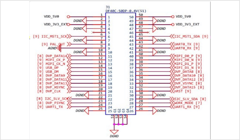
Figure1 Module Product Pin Diagram A
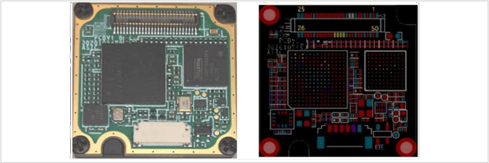
Figure2 Module Product Pin Diagram B
Table3 HIROSE 50-Pin Connector User Interface Definition
| Pin Number(s) | Pin Name | Type | Description |
|---|---|---|---|
| 20, 33, 19, 32, 11, 18, 34, 17, 35, 16, 36 | DVP_CLK, DVP_VSYNC, DVP_HSYNC, DVP_DATA15~8 | Output | DVP data signal DATA15:MSB DATA8:LSB |
| 12, 13, 40, 39, 38, 37 | MIPI_CK_P/N, MIPI_D0_P/N, MIPI_D1_P/N | Output | 2-lane MIPI data signal |
| 14, 15 | USB_DP, USB_DM | Output | USB 2.0 data signal |
| 8, 9 | PAL_OUT, AGND | Output | Analog output signal / Analog output ground |
| 43, 42 | UART0_TX, UART0_RX | Output | General-purpose communication serial port pins, can be used to control the module |
| 24, 27 | UART1_TX, UART1_RX | I/O | Transmit/Receive pins for the debug serial port (can print module running log); can also be used as general-purpose I/O |
| 22, 29 | I2C_SLV_SCK, I2C_SLV_SDA | I/O | IIC slave clock pin / IIC slave data pin |
| 6, 45 | IIC_MST1_SCK, IIC_MST1_SDA | I/O | IIC master clock pin / IIC master data pin |
| 23 | DVP_FSYNC | I/O | External synchronization input signal for the module (not the DVP output sync signal); can also be used as general-purpose I/O |
| 28 | WORK_MODE | Input | Set high to enter update mode; can be left floating in hardware design if not used |
| 31 | Nrst | Input | Set low to enter reset mode; can be left floating in hardware design |
| 1, 50 | VDD5.0 | Power | External 5V power input; the module can operate normally with a single 5V supply |
| 3, 48 | VDD3.3 | Power | External 3.3V power input (reserved for potential use; actually requires no power supply in practice) |
| 2, 4, 7, 10, 21, 25, 26, 30, 41, 44, 47, 49 | DGND | Power | Ground |
| 5, 46 | NC | NC | Not for user use |
Note1: Pin numbering in the table corresponds to the pin name sequence.
Note2: DVP and IIC slave voltages default to 1.8V and can be switched to 3.3V via command.
Note3: UART0, UART1, and IIC master voltages are fixed at 3.3V and cannot be switched.
Note4: Hardware descriptions are for reference only. Contact technical support for detailed development materials.
Note5: CVBS only supports black and white hot switching.
Mechanical Dimensions
Note: The following examples show the NTIR-384 lens-free module and NTIR-384 9.1mm lens module. For 2D/3D drawings, contact technical support.
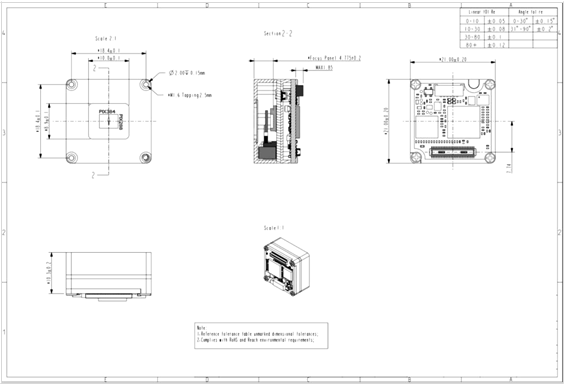
Figure3 NTIR-384 Lensless Module Structure Diagram
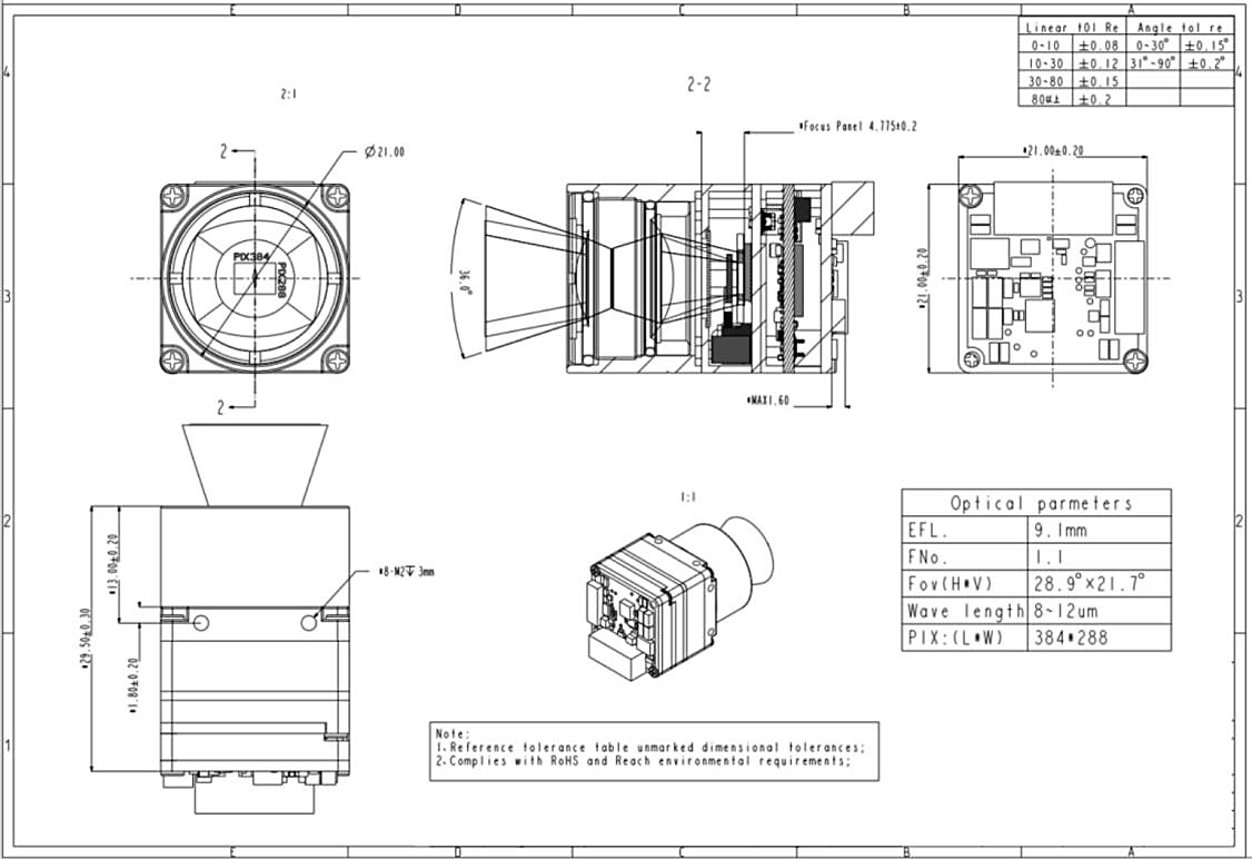
Figure4 NTIR-384 9.1mm Lens Module Structure Diagram
Precautions
To prevent injury or device damage, adhere to the following:
• Do not point the module at high-intensity radiation sources (e.g., the sun).
• Ideal operating temperature: -40°C ~ 80°C.
• Avoid touching the device or cables with wet hands.
• Do not bend or damage cables.
• Do not clean the device with thinners.
• Do not plug/unplug cables while powered on.
• Avoid incorrect cable connections to prevent damage.
• Take anti-static measures.
• Do not disassemble the device. Contact the manufacturer for repairs.
Quality Warranty & Support
The company provides pre-sales training, in-development support, and post- sales module maintenance. Contact sales representatives for details.
Tel: +86 18608017948(WeChat)
E-mail: marketing@newtron-tech.com


Fill in your e-mail: